Database Design
Subject: Microservice Programming (VU-CSS 325)Database design is the systematic process of organizing and structuring data so that it can be stored, retrieved, and managed efficiently in a database system. A well-designed database ensures data accuracy, reduces redundancy, improves performance, and supports scalability as an application grows. Poor database design often leads to duplicated data, inconsistencies, slow queries, and difficulty in maintaining or expanding the system.
1. Efficient (fast queries, minimal redundancy)
2. Consistent (data integrity is maintained)
3. Scalable (can grow with future needs)
4. Logical (easy to understand and maintain)
Main Stages of Database Design
1. Requirement Analysis: database design process typically begins with requirements analysis. At this stage, the designer identifies what data needs to be stored, who will use the system, and what operations will be performed on the data, such as creating, reading, updating, or deleting records. Understanding user needs and system goals at this early stage is critical because mistakes made here often affect the entire database structure.
Before touching SQL, ask:
- What data do we need to store?
- Who will use it?
- What operations are required? (create, read, update, delete)
- How often will data change?
For example, student management system; you need students, courses, enrollments, lecturers, grades.
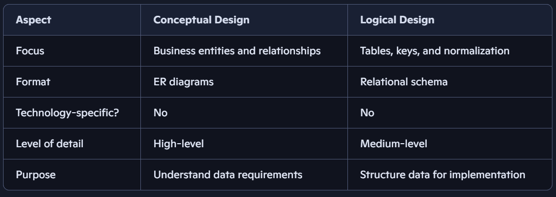
2. Conceptual Design:after gathering requirements, the next step is conceptual design. This stage focuses on identifying the main entities in the system, their attributes, and the relationships between them. Conceptual design is usually represented using Entity–Relationship (ER) diagrams and is independent of any specific database management system. For example, in a student management system, entities such as Student and Course are identified, along with attributes like student name, and email, and relationships such as student enrollment in courses.
- Identify entities (objects) e.g Student, Course
- Identify attributes (properties) e.g student_name, email; course_name, department_id
- Identify relationships: e.g Student enrolls in Course. Courses are related to Departments
Note:
- This is the high-level blueprint of the database, focused on what data needs to be stored.
- To capture the business requirements and structure them into a clear model.
3. Logical Design: The logical design phase translates the conceptual model into a structured schema composed of tables, columns, and keys. During this stage, primary keys are defined to uniquely identify records, and foreign keys are introduced to establish relationships between tables. Normalization is also applied at this level to organize data efficiently and eliminate redundancy. Logical design remains independent of the physical database engine but closely resembles the final table structure.
Note:
- This is the technical translation of the conceptual model into a relational schema.
Key Features:
- Converts entities into tables.
- Specifies primary keys, foreign keys, and data types.
- Applies normalization rules to reduce redundancy.
- Still independent of physical storage or specific DBMS.
Goal:
To prepare a detailed schema that can be implemented in any relational database system.
4. Physical Design: physical design is the final stage of database design and deals with how the database will be implemented in a specific database management system such as MySQL, PostgreSQL, or SQL Server. This stage includes choosing appropriate data types, creating indexes, defining constraints, and considering storage and performance optimization.
Core Database Design Concepts
1. Tables: a table in a Relational Database Management System (RDBMS) is a structured collection of data organized into rows and columns.
- Each row (record) represents a single entry.
- Each column (field) represents an attribute of the data.
- Example: A Students table might have columns like StudentID, Name, Age, Course.
2. Keys:
Keys are Define Relationships
a. Primary Key (PK): unique identifier for each row in a table. e.g StudentID or MatricNumber
b. Foreign Key (FK): A column in one table that refers to the Primary Key in another table; they are use to create relationships between tables.
Example:
• In students table, StudentID field is a Primary Key
• In enrollments table, StudentID field is a Foreign Key referencing Students(StudentID)
3. Relationships:
Relationships define how tables are connected. They are established using keys (Primary Key, Foreign Key).
a. One-to-One (1:1)
• Each row in Table A relates to exactly one row in Table B.
• Example: Students table and StudentAddress table (each student has one unique address). OR One user can only have one profile
b. One-to-Many (1:N)
• 1 row in Table A can relate to many rows in Table B.
• Example: Courses table and Students table (one course can have many students).
c. Many-to-Many (M:N)
• Many rows in Table A can relate to many rows in Table B, and vice versa.
• Example: Students and Subjects (a student can take many subjects, and a subject can be taken by many students).
ER diagram
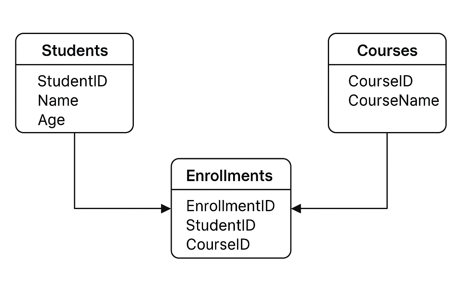
A Students

Conceptual Design & Logical Design
By: Vision University
Comments
No Comment yet!
Login to comment or ask question on this topic
Previous Topic Next Topic
- 1 Introduction to Microservices
- 2 Introduction to API
- 3 Database Design
- 4 Introduction to MySQL
- 5 Building CRUD API using Flask and MySQL